Approaches for Charger Testing
Overview
Chargers manage voltage and current to refill or recharge a battery according to the manufacturer’s specifications. While simple in concept, a charger may be required to change its output characteristics, detect, and test batteries before or during charge, or even require communication with the battery or the utility company. Chargers range from a simple charger which provides only a constant current (CC), constant power (CP), or constant voltage (CV) output all the way up to a grid-managed charger which changes how it charges the battery based on utility, battery, and additional conditions.
Let’s discuss the different ways to test each type of charger.
Contents
- Always-On Chargers
- Waking Up a Charger
- Chargers that “Test” the Battery During Charge
- Charger Output Controlled by BMS Data
- Charger Output Modified by Grid Use
- Vehicle-to-Grid Power Transfer
- How NI Equipment Meets AC and DC Charging Needs
- Next Steps
Always-On Chargers
Always-on chargers typically provide a fixed output. For example, a lead acid trickle charger provides only a small constant current (CC) output. This type of charger can be verified by using an electric load with either constant voltage (CV) or constant resistance (CR).
In rare cases, this type of charger may provide either CC or CV during the charge profile. In this case, the electronic load can still be used by using a constant resistance (CR) loading. NI loads offer CC, CV, and CR allowing maximum flexibility in evaluating always-on chargers.
Waking Up a Charger
The battery charger may not provide an output voltage or current until it first detects the voltage from the battery, an external interlock is closed, or both. The charger may even use these battery detection conditions to determine how to safely start charging the battery. For example, the charge profile may wait until the temperature reaches an acceptable level or contain additional precharge steps to recover deeply discharged batteries.
In these cases, the test fixture may contain a small power supply, or relays needed to “wake-up” the charger. NI air-cooled loads provide digital I/O allowing additional test fixtures devices to managed by the load.
NI provides connections that allow a turn-on signal to be used for a charger or a small power supply, or you can control a relay/switch to connect the power supply to the charger to start it up then disconnect it later.
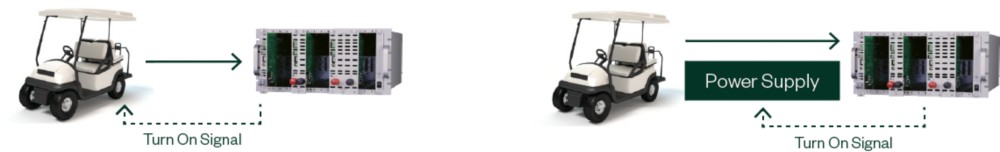
Figure 1: Examples of turn-on signal connections
Chargers that “Test” the Battery During Charge
Chargers may “test” the battery during charge by reducing or even drawing power from the battery itself. Some types of batteries require these “tests” for the charge to be properly accepted, to reduce internal pressure, or to reabsorb chemicals within the battery itself. Alternatively, some chargers do these “tests” to safely charge the battery, to determine the health of the battery, or for self-calibration of the charger itself. How the charger “tests” the battery and what the charger expects to see in a normal battery determine the approach used in validation.
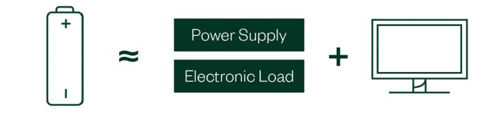
Figure 2: Combining a Source and Load with a Control PC
Combining an NI load with a power supply along with a control application on a PC is a cost-effective solution for low-power chargers (<6 kW) especially when the charger does not require a quick response from the simulated battery. In this case, the PC adjusts the power supply and load to simulate the increasing battery voltage as it is being charged.
In this scenario, you can program the PC to control the power supply and load to emulate how a battery actually behaves any time the charger performs a “test” of the battery. In this case, the PC continuously measures the voltage and current being delivered by the charger and adjusts the power supply and load to emulate the battery response. This process is then repeated throughout the entire simulated charge profile.
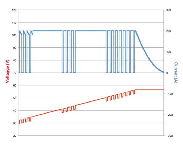
Figure 3: Relationship between battery voltage and charge current
A more direct approach can be implemented by first understanding why a battery changes its voltage from changes in charge current. The voltage seen at the terminals of a battery decreases slightly as a charger reduces or even reverses the charge current. Similarly, the voltage at the terminals of a battery increases slightly as the charger supplies additional current. Both effects are caused by the internal resistance of the battery chemistry and the wire connections.
The NI medium- and high-power battery cycler/emulators provide a battery mode. This mode enables you to program the series resistance (RS) and a no- load open circuit voltage (VOCV). When programmed, the system automatically adjusts the output terminal voltage based on the direction and level of current flowing to, or from, the charger.
The adjustment is handled in the hardware improving the simulation speed, removing the integration complexity, and allowing the PC to focus on the test. In addition, the charger remains in control of the terminal voltage and current even when it changes between CC, CP, or CV.
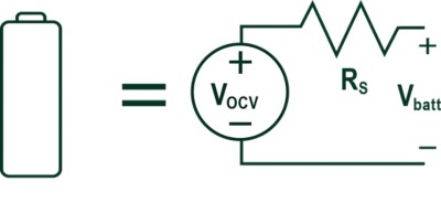
Figure 4: Equivalent Battery Model

Figure 5: Formula for Battery Model
Charger Output Controlled by BMS Data
A charger changes its output to meet the manufacturers requirements properly. Many chargers today communicate with the battery, utility company, or both. Charging stations may enable power by stabilizing frequency, reducing peak demand spikes, or providing temporary backup.
The charger that communicates with the battery management system (BMS) adjusts its output based on the battery data information returned. This approach is found in chargers of all sizes including laptop, in-vehicle chargers, and wireless power transfer systems.
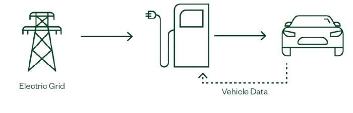
Figure 6: Example of a fast-charging system for EVs
The test station needs to emulate the battery and provide a communication interface such as I2C, SMBUSS, or CAN to communicate with the charger-under-test.
Charger Output Modified by Grid Use
Charger output may also change because of current electric grid utilization. These grid-aware chargers may adjust their output, reducing, pausing, or even delaying charging. These chargers can communicate with a smart grid using standard-based protocols like the smart energy profile (SEP).
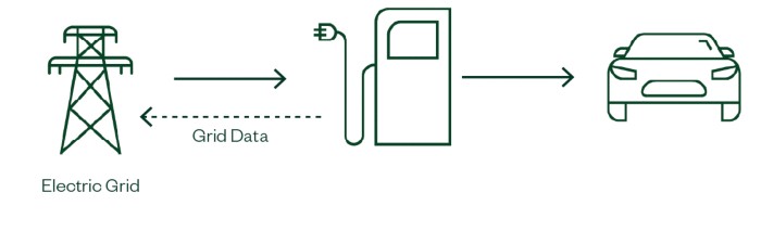
Figure 7: Example of a Utility-Managed Charging System for EVs
Vehicle-to-Grid Power Transfer
A number of initiatives exist for using vehicles as local backup power or to assist the utility company during periods of peak demand. In these cases, the charger is reversed and acts as a distributed generator taking power from the battery and supplementing the electric grid to address short-term power shortages, frequency shifts, or other grid issues.
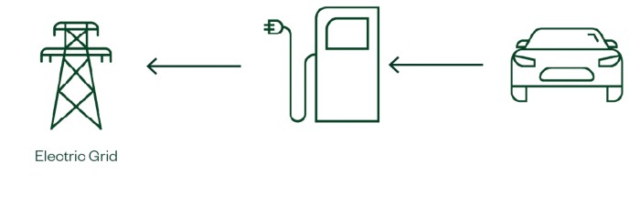
Figure 8: Example of a vehicle-to-grid system where the EV charger is reversed and acts as a distributed power generator.
NI supplies software packages and fully documented drivers, allowing them to be added to test setups for any of these applications.
How NI Equipment Meets AC and DC Charging Needs
The International Standard for Electric Vehicle Conductive Charging Systems (IEC 61851-1) has defined four modes of EV charging1. NI's DC and AC power test solutions emulate real-world conditions and are critical for the testing and validation of EV components and systems. Based on the charging mode, the test solution you choose will vary.
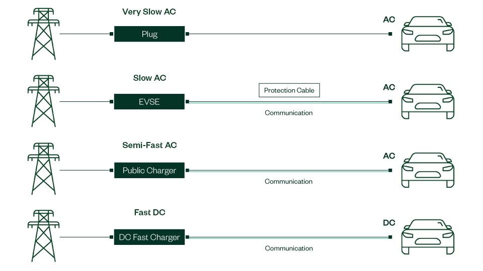
Figure 9: From top to bottom, EV charging Mode 1 through 4
AC Charging
Mode 1: Very Slow AC Charging
Mode 1 is very slow AC charging, typically from a standard, residential AC outlet with up to 16 A. The charging is direct to the onboard charger (OBC), with no communication.
Mode 2/Mode 3: Slow-to-Semi-Fast AC Charging
Mode 2 is slow AC charging with a maximum of 32 A, whereas mode 3 is semi-fast AC charging at up to 80 A. In these modes, alternating current (AC) is supplied to the onboard charger (OBC), which is the battery charger, using the Electric Vehicle Supply Equipment (EVSE) protocol. The charging ranges from 6 kW to 22 kW in Mode 2 for residential charging and 44 kW in Mode 3 for public charging stations. Both modes control charging with communication functions; in mode 2, cable signaling provides the control, and in mode 3 both cable signaling and communication protocols are used. These modes typically have a lower infrastructure cost and higher availability, as compared to Mode 4. However, the use of the OBC can reduce the max charging rate, unlike Mode 4, which doesn’t use an OBC.
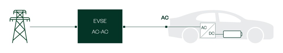
Figure 10: Slow-to-semi-fast AC charging components
For AC charging, NI offers the following equipment:
- NHR-9410 Regenerative Grid Simulator System simulates the utility grid.
- NHR-9430 Regenerative AC Load System emulates the AC loading.
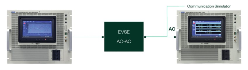
Figure 11: AC charging equipment
DC Charging
Mode 4: DC Fast Charging
Mode 4 is fast DC charging, typically from a public charger. In mode 4, DC power directly charges the battery. In this mode, since there is no OBC, the charging can be very high power, ranging from 50 kW up to even greater than 300 kW. This fast, high-power charging requires a higher infrastructure cost and higher complexity, including the need for cable signaling and communication protocols.
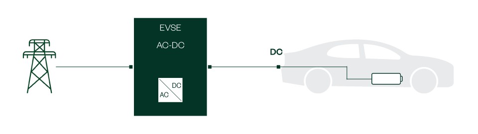
Figure 12: DC fast charging components
For DC charging, NI offers the following equipment:
- NHR-9410 Regenerative Grid Simulator System simulates the utility grid.
- NHR-9200 Mid-Voltage DC Battery Module Cycler and Emulator and NHR-9300 High-Voltage DC Battery Pack Cycler and Emulator mimic the battery or the DC fast charger.
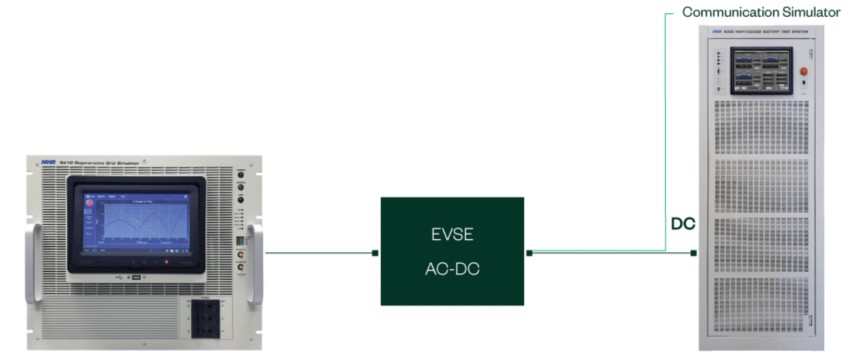
Figure 13: DC charging equipment
Grid Simulation and Emulation (Onboard Charger and Vehicle-to-Grid)
In EV charging applications, test engineers rely on using a battery emulator to test components like the OBC. By pretending an actual battery is connected to such components, engineers can test in a faster, safer, and repeatable environment. NI provides flexible and modular battery test solutions that you can use to simulate or emulate the different modes of EV charging featuring fast transient capabilities, regenerative power, built-in safety isolation relays, contactors, and more.
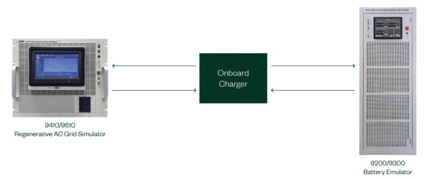
Figure 14: Onboard charger equipment
- NHR-9410 Regenerative Grid Simulator System simulates the utility grid.
- NHR-9200 Mid-Voltage DC Battery Module Cycler and Emulator and NHR-9300 High-Voltage DC Battery Pack Cycler and Emulator mimic the battery or the DC fast charger.
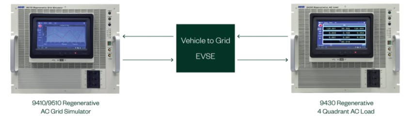
Figure 15: Vehicle to grid (V2G) charging equipment
- NHR-9410 Regenerative Grid Simulator System simulates the utility grid.
- NHR-9430 Regenerative AC System emulates the AC loading.
1. SAE defines these charging modes as levels: Level 1=Mode 1, Level 2=Modes 2 and 3, and Level 3=Mode 4